Are you ready for the reduction in export tax rebates for lithium batteries?
2026-03-25 15:18:10

Are you ready for the reduction in export tax rebates for lithium batteries?
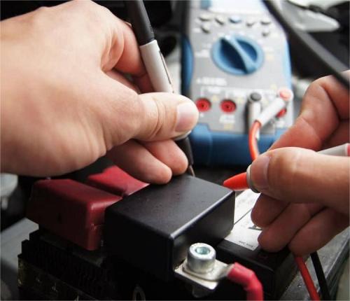
Lithium-Ion Battery Care Guide

The Middle East Situation's Repercussions on Maritime Shipping
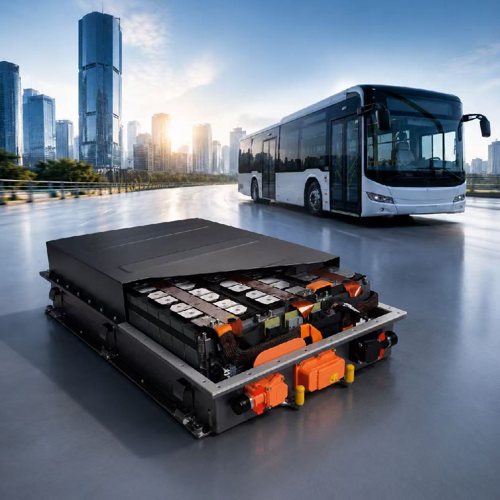
Reliable Battery Solutions Powering the Future of Electric Buses
Achieving fast charging for forklift lithium-ion batteries requires a systematic design based on the chemical characteristics of LFP and the opportunity charging conditions of forklifts.
I. Cell-Level Hardware Foundation (Material Selection)
1. High-Rate LFP Cell Selection
Positive Electrode Material: Nanoscale lithium iron phosphate (particle size <200nm) is selected to shorten the Li⁺ diffusion path and support 2C-3C continuous charge and discharge.
Negative Electrode Optimization: Artificial graphite + carbon black composite (instead of pure graphite) is used to improve conductivity; or slight silicon doping (<5%) is used to balance energy density and rate.
Electrolyte: High conductivity electrolyte is used (LiPF6 concentration 1.2-1.5M, with the addition of LiFSI dual salt system) to reduce concentration polarization.
Taper Design 1. Multi-tab/All-tab (Tabletless) Structure: This reduces internal resistance to <1mΩ (compared to 2-3mΩ for traditional monopole charging), thus lowering heat generation.
2. Temperature Management System (The bottleneck of fast charging is heat): Forklifts are typically air-cooled or forced-air-cooled (without liquid cooling), requiring targeted design.
3. BMS Software Strategy (Intelligent Current Limiting Algorithm):
1. Step-down CC-CV Charging:
2. SOC Estimation and Calibration: Forklifts operate under shallow charge and discharge conditions (PSOC, 20%-80%), leading to accumulated errors from traditional coulomb metering. The following features need to be introduced:
1. Kalman filter algorithm: Real-time correction of SOC to avoid "false charging" (displaying 100% when not actually full)
2. Regular open circuit voltage (OCV) calibration: Weekly deep discharge to 20% to calibrate SOC and ensure accurate triggering of fast charging strategy
3. Intelligent recognition of opportunistic charging
If plug-in time is detected to be <30 minutes (during a break), force activation of 1C fast charging mode (recharging to 80%)
If plug-in time is detected to be >2 hours (night shift charging), switch to 0.5C slow charging mode (fully charging to 100%, extending lifespan)
IV. Charging pile/charger matching (electrical interface)
1. Charging protocol
Use CAN bus communication (compliant with CHAdeMO or GB/T 27930 protocol) to achieve:
Active battery request current demand (not constant voltage output from the charger)
Real-time upload of cell temperature, with the charger dynamically adjusting its output
2. Voltage platform matching
Your company needs to ensure that the charger supports a wide voltage range (e.g., 40V-100V) to adapt to different vehicle models. 3. Connector Selection: Use Anderson SB/SRE series or REMA Euro connectors. DIN interface, rated current 320A-480A
Key: Silver-plated contacts (not nickel-plated) to reduce contact resistance (<0.1mΩ) and prevent overheating and burning during fast charging
V. Pack Structure-Level Design (Physical Implementation)
1. Copper/Aluminum Busbar Specifications
Main circuit copper busbar cross-sectional area ≥25mm² (6-8mm² required per 100A) to prevent ohmic heat (I²R loss)
Laser welding (not screw connection) is used to reduce contact resistance
2. Fuse and Relay Derating
During fast charging, the current fluctuates greatly. The main relay (contactor) should be selected according to 1.5 times the rated current (e.g., for continuous 200A, select a 300A contactor).
Fast-blow type (gG type) fuses should be selected to avoid accidental melting due to peak fast charging current.
3. Balancing Strategy
During fast charging, the voltage difference between cells will amplify. Active balancing (energy transfer type, not resistive dissipation) needs to be enabled to control the voltage difference within 30mV to prevent single cell overvoltage protection (OVP) from triggering charging stop.